ECOO '98 - Session H5 - Interfacing: Have Your PC Talk to the Real World

John Childs - Grenville Christian College - Brockville, ON

(ECOO : Educational Computing Organization of Ontario)

LED Bar Construction Details


The purpose of this document is to give detailed instructions for the construction of an "LED Bar." This device is shown here, and is plugged into the parallel port of a PC. With the proper code, it illustrates sending signals to the parallel port and lighting the LED's in any desired pattern. It contains 8 LED's, each driven by one of the data lines of the parallel port. (D0...D7) Each LED is switched on by a transistor. To keep the current supplied by the parallel port to 2 mA per line or less, the base of each transistor is in series with at 2.2 k ohm resistor, and each LED is in series with a 10 ohm resistor. The LED's receive power from 3 AAA batteries, and NOT from the parallel port. The LED Bar gives an excellent display of binary counting, and is a fun device for which to write code. Many, many different modes of flashing lights are possible.


CONSTRUCTION DETAILS

All up, down, left and right directions assume that you are looking at the bottom of the u-shaped tube.

1. Locate the 16 holes on the inside of the tube. Use an awl to make a dimple to mark the exact centre point of each hole location. This will keep the drill bit from "wandering" when you drill the holes for the LED's and the transistors.

2. Place the tube on a piece of scrap wood and drill 16 holes . Use a 3/16" bit. (This size is just right for many LED's and transistors. Test on a piece of scrap plastic if necessary.) The holes are toward the right side, and the blank area to the left is where the three batteries will be positioned.

Note: a 2n3904 transistor has an arrangement of E-B-C for the wire leads, looking at the flat side, wires down. This is different than the conventional arrangement of E-C-B for a generic transistor. Make sure you get it right!

3. Press 8 transistors (almost any NPN type will do) into the bottom row of holes. N.B. Keep the flat side of the transistor toward the bottom tube edge. Some transistors may fit loosely, others might be hard to get into the hole. Position them so the top of each sticks out of the hole the same amount. Put a tiny dab of super glue on the flat side of each transistor to hold it in place.

4. Press the right hand leg (collector) of each transistor to the bottom of the tube and raise theother two legs (base and emitter) up to get them out of the way.

5. Strip half of the insulation off each of the 20 cm. long wires. Run the wire along the bottom of the tube, so it is in position to solder each bent down transistor leg to it. Put a dab of flux on the right most transistor leg and solder it to the right hand end of the wire. Put a dab of flux on each of the other seven joints and solder each transistor leg that has been bent down to this wire. Cut off excess leg length, being careful not to have little pieces of wire fly into your face, or stay in among the wires.

6. Cut the centre leg (base) of each transistor so that it is about 1 cm. long. (i.e. Cut the leg roughly in half.) Be careful of flying wire bits!

7. Press 8 LED's into the top holes. N.B. Be sure that the flat side of the LED, (marking thenegative leg) is toward the centre of the tube. Put a tiny dab of super glue on the edge of each LED to glue it in place.

8. Cut the top (+) leg of each LED so it is only about 1cm. long. N.B. Eye danger! Don't let little pieces of wire fly into the air!

9. Bend the left leg of each transistor off to the left at about a 45ø angle. Bend the long leg ofeach LED to the left so it reaches over and touches the left leg of the transistor opposite it. It is very helpful to have the wires touching, before you solder. Use the natural springiness of the LED legs to have their bent position hold them against the transistor leg.

10. Put a dab of flux on each joint, solder, and cut off the excess lengths of wire. (Watch outfor flying bits of wire.)

11. All 16 resistors need to have their legs cut down to very short lengths. Cut one side short,and after soldering each, trim the other. The amount of wire protruding from each end of eachresistor only needs to be 3 or 4 mm.

12. Using the picture as a guide, solder the 10 ohm resistors to the LED's top leg. Dip one end of the resistor wire in flux, and use it to brush a little flux onto the LED wire. (10 ohm = brown,black, black. Either end can attach to the LED, resistors have no polarity.) It might be helpful to prop the tube up so that the short LED wire is horizontal. Solder the 2.2k ohm resistors (red, red,red)to the middle leg (base) of the transistor.

13. Take the other long piece of wire and solder it to each of the 10 ohm resistors. This wire runs back to the batteries. Don't forget to use little dabs of flux.

14. Take the piece of flat ribbon cable and separate the individual strands on one end for about 10 or 12 cm. Leaving one at its full length, cut each of the others about 1 cm shorter than the one next to it. Strip off about 2 mm of insulation on each wire, dip the bare wire into the flux, and apply a dab of solder to the wire end before soldering it to the top of the 2.2 k ohm resistor. Put a dab of flux on the top of each 2.2 k ohm resistor and solder each ribbon wire to its respective resistor. The ninth wire, along the outside edge of the ribbon cable, gets soldered at any point to the long wire that joins the transistors.

15. Tape up three AAA batteries side by side with ends reversed. Have the bottom battery + to the right, the middle battery + to the left, and the top battery + to the right. Put a dab of flux on each end terminal of each battery, and solder a dab of solder on all six ends. Now that the battery terminals are prepared, trim 1 cm. of wire off each long wire in your kit, and use them to wire the batteries in series. Solder the + terminal of the bottom battery to the - terminal of the middle battery, and the + terminal of the middle battery to the - terminal of the top battery. Use some black electrical tape to wrap the batteries into the tube, as shown below. Solder the long wire joining the LED resistors to the + terminal (right end) of the top battery, and the long wire that joins the transistors together to the negative terminal (left end) of the bottom battery. Polarity is important!

16. Separate the 9 individual strands of the other end of the ribbon cable for 1 or 2 cm. Strip 1mm of insulation off the end of each wire. Prepare these ends by dipping each bare wire into the flux, and applying a dab of solder to each.

17. Be sure to identify which wire goes to the LED at the right hand end of the tube. This is LED #1, and this wire must be connected to pin number 2 in the DB25 connector. Put a dab offlux on each pin lug, and solder in each wire. They go in succession to pins numbered 2 to 9 (D0..D7) (If you look carefully, you will see that the pins are numbered.) The wire along the other edge of the ribbon cable, the one soldered to the long wire that joins the transistors, gets soldered to pin number 25, which is ground, of the DB25 connector. (Actually, you could solder it to any
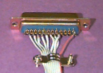
of pins 18 - 25, as they are all connected to ground via the parallel port.) Connect the strain relief clamp (as shown) and attach the plastic case to the DB25 plug. (The plug kit contains two screws and shaped metal tabs that allow the DB25 connector to be semi-permanently held in place. Since your LED Bar will typically be a temporary connection, you can discard these parts.)

Carefully double check all your electrical connections and make sure there are no little pieces of wire left inside, or that any wires got bent into positions that allow unwanted contact. Fasten the black tube to the wooden base using the two small screws. You're finished! :-)) For your very first test, use any OLD computer. For computer interfacing, the advice "better safe than sorry", really applies!


Running your LED Bar.


Each language has a command that controls the status of the data lines on the parallel port.
QuickBASIC:
The OUT command. It has the syntax OUT(###), decimal value. The number in brackets is the base address of the printer adapter. On some computers it is 888, on my IBM laptop, it is 956. Example: OUT(888), 255 should light all 8 LED's. OUT(888),0 will turn them all off.
Turing:
The PARALLELPUT command. It has the syntax PARALLELPUT(decimal value).
Example: PARALLELPUT(255) will light all 8 LED's.
Pascal:
The PORT command.
PORT[888] := 255; or PORT[$378] := $FF; {hex $378 = decimal 888, hex $FF = decimal 255 }

The following paragraph is excerpted and adapted from Tom Dickinson's faq page which can befound at: http://www.ece.uiuc.edu/~ece291/class-resources/parallel.html and should be considered required reading for anyone interested in the details of parallel port interfacing.
To find the address of the LPT1 port on a PC, use DEBUG. At a DOS prompt, type debug. You will get a minus sign, (not blinking) at the left edge of the screen which is the debug prompt. Type the following (with no spaces): d40:0008 and hit enter. You will see something like:
0040:0008 78 03 00 00 00 00 00
and several more lines of similar numbers and letters. This is a "hex dump" of the contents of the eight memory locations starting with 40:0008. The first pair of numbers (78 03) is the base address of LPT1. The number pair 78 03 is the hex number 0378h. The 78 and the 03 are reversed because Intel stores sch numbers in a 'low byte-high byte' format. If only one printer adapter is stored, the following numbers will be 00 00 etc. If your PC has an LPT2, and/or LPT3 installed, there will be other pairs of numbers on the 0040:0008 line. You can exit debug by typing q.
Convert your hex number to decimal. For example: 0378 = (8 x 1 = 8), + (7 x16 = 112), + (3 x256 = 768). 8 + 112 + 768 = 888.
The following web sites have excellent information and links, and will keep you busy for the nextcouple of hundred years!
Or, just do any web search on "parallel port interfacing" and you fill find a flood of useful info!

The following is a QuickBASIC program that illustrates the use of the OUT command to run yourLED Bar. Change the value of Delay in the last SUB to suit your computer.
DECLARE SUB Count ( )
DECLARE SUB Menu ( )
DECLARE SUB LicensePlate ( )
DECLARE SUB Pause ( )
DECLARE SUB Bounce ( )
DECLARE SUB SetUp ( )
DECLARE SUB Running ( )
DIM SHARED Lt(8), Delay, Ch$, Row, Col, LPTaddress
CLS
CALL SetUp
OUT (LPTaddress), 0
DO
CALL Menu
IF Ch$ = "R" THEN CALL Running
IF Ch$ = "B" THEN CALL Bounce
IF Ch$ = "L" THEN CALL LicensePlate
IF Ch$ = "C" THEN CALL Count
LOOP UNTIL Ch$ = "Q"
OUT (LPTaddress), 0
PRINT "end"

SUB Bounce
LOCATE Row, Col: PRINT "Bounce"
DO
FOR N = 2 TO 8
'PRINT N
OUT (LPTaddress), Lt(N)
FOR X = 1 TO Delay: NEXT X
NEXT N
FOR N = 7 TO 1 STEP -1
'PRINT N
OUT (LPTaddress), Lt(N)
FOR X = 1 TO Delay: NEXT X
NEXT N
LOOP UNTIL INKEY$ <> ""
OUT (LPTaddress), 0
END SUB

SUB Count
LOCATE Row, Col: PRINT "Counting"
PRINT "Continuous or Keyboard paused? (c/k)"
DO
Ch$ = UCASE$(INKEY$)
LOOP UNTIL Ch$ = "C" OR Ch$ = "K"
IF Ch$ = "C" THEN
INPUT "Delay amount... : "; Amount
END IF
FOR N = 1 TO 255
PRINT N;
OUT (LPTaddress), N
IF Ch$ = "K" THEN SLEEP
IF Ch$ = "C" THEN
FOR Delay = 1 TO Amount
NEXT Delay
END IF
NEXT N
SLEEP
OUT (LPTaddress), 0
END SUB

SUB LicensePlate
LOCATE Row, Col: PRINT "License Plate"
DO
OUT (LPTaddress), 8 + 16: Pause
OUT (LPTaddress), 4 + 32: Pause
OUT (LPTaddress), 2 + 64: Pause
OUT (LPTaddress), 1 + 128: Pause
OUT (LPTaddress), 2 + 64: Pause
OUT (LPTaddress), 4 + 32: Pause
LOOP UNTIL INKEY$ <> ""
OUT (LPTaddress), 0
END SUB

SUB Menu
CLS
PRINT "R)unning"
PRINT "B)ounce"
PRINT "L)icense Plate"
PRINT "C)ount"
PRINT
PRINT "Q)uit"
DO
Ch$ = UCASE$(INKEY$)
LOOP UNTIL Ch$ <> ""
END SUB

SUB Pause
FOR X = 1 TO Delay: NEXT X
END SUB

SUB Running
LOCATE Row, Col: PRINT "Running"
DO
FOR N = 1 TO 8
'PRINT N
OUT (LPTaddress), Lt(N)
FOR X = 1 TO Delay: NEXT X
NEXT N
LOOP UNTIL INKEY$ <> ""
OUT (LPTaddress), 0
END SUB

SUB SetUp
CLS
PRINT "LED display"
PRINT
LOCATE 3, 3
PRINT "Typical desktop = 888"
LOCATE 4, 3
PRINT "IBM ThinkPad = 956"
LOCATE 2
INPUT "Enter parallel port number... : "; LPTaddress
Row = 9
Col = 9
Delay = 30000
FOR N = 0 TO 7
Lt(N + 1) = 2 ^ N
'PRINT Lt(N)
NEXT N
CLS
END SUB


LED Bar : General Notes


Soldering - a personal perspective:
This is a skill that takes some time to develop. The single greatest technique that enhances successful soldering is the use of flux. It is seldom mentioned in handbooks, but it makes all the difference in the world. You will often hear the comment that many, if not most electronic solders have a hollow core that is filled with flux. (Rosin core.) Forget it. I find that the amount it provides is almost useless compared to a dab applied separately before soldering. If you are soldering without flux, try some and note the difference. You'll be amazed. :-) A well soldered joint has a smooth and glossy appearance. A poor joint has the solder beading and bunching up and looking like a pile. The purpose of the flux is to clean the surface and allow the solder to adhere to the surface. Flux will remove the invisible oxidation layer on a metal surface that can make it impossible to solder. Solder will flow onto a surface that is HOT. Your soldering iron tip must be kept clean which allows it to transfer heat to the joint being soldered. If corrosion builds up on the tip, clean it by lightly touching it to the flux, and apply a tiny bit of solder. When the tip gets very dirty, use a few stokes of steel wool or emery cloth. An easy way to transfer heat and solder to a wire joint is to first dip each wire into the flux and position them. Then touch the soldering iron to the solder and pick up a tiny drop of solder. It will cling, melted, to the tip of the iron. Now just touch the wire joint and the solder will flow onto it. This only takes a fraction of a second. Remove the iron as soon as you see the solder flow, and blow on the joint. (Try not to inhale the flux fumes!) Cooling and solidification takes about a half second. Try and apply the least amount of heat possible. The wires get hot, and excessive heat can damage some electronic components. Your solder joints should be able to be completed with the soldering iron touching the parts for only a fraction of a second. If you have to keep touching the connection over and over, for several seconds, you will definitely need to refine your technique!
Parts:
These parts can be obtained at any electronics supply. While Radio Shack is good for small quantities, an excellent source for larger quantities is:

Electrosonic Inc., 1100 Gordon Baker Rd., Willowdale, ON M2H 3B3 1-800-56-SONIC
They have a 2,000 page catalogue. I usually receive an order within 24 hours. :-)
ItemStock #Cost
LED's 279 55-552-0$11.83/100
Transistors111 2N3904$ 0.14 each
Carbon Film Resistors353 CR25 2.2K$ 1.00/100
Carbon Film Resistors353 CR25 10$ 1.00/100
DB25 plug279 30-112-0$ .75 each
DB25 hood279 30-132-0$ .57 each
Beldon flat cable (10 conductor)9L28010$14.00/100 feet

The black plastic tubes are from a Canadian Tire Plumb Pak: 17.75" Extension drain tube. ($5) Cut it into two pieces 8.75+" long with a hack saw. (Use a new blade with small teeth.) Cutting each short tube into half tubes is a little harder. I used a band saw and a little jig to keep things straight.
If you have any questions about this device I will be glad to correspond with you to answer any questions.(john.childs@cogeco.ca) If you build one let me know! :-)
Created: 4/20/98 Updated: 8/11/07